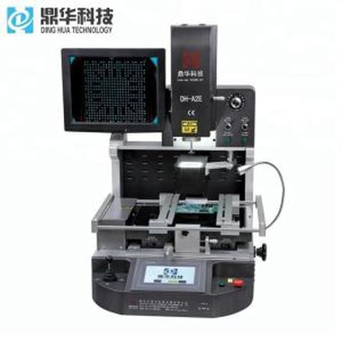
Automatic BGA IC Chips Remove Machine
BGA rework stations are used for soldering and desoldering of unit parts on the Printed Circuit Boards (PCBs). Unit parts are normally clustered in a very small section of a PCB and will require heating of the board in that particular area. To handle such critical and sensitive work/rework where there is a chance of parts getting damaged our BGA rework stations like DH-A2E.
Aprašymas
Automatic BGA IC Chips Remove Machine
1.Application of Automatic BGA IC Chips Remove Machine
Motherboard of computer, smart phone, laptop, MacBook logic board,digital camera ,air conditioner, TV and
other electronic equipments from medical industry, communication industry, automobile industry, etc.
Suitable for different kind of chips: BGA,PGA,POP,BQFP,QFN,SOT223,PLCC,TQFP,TDFN,TSOP, PBGA,CPGA,
LED chip.
2.Product Features of Automatic BGA IC Chips Remove Machine

• Highly efficient, long-life 400 W hybrid heating head
• Optional with 800 W IR-bottom heating
• Very short soldering times feasible
• Activation with safety foot switch
• Operation LEDs on the system
• Intuitive operation without software
3.Specification of Automatic BGA IC Chips Remove Machine

4.Details of Automatic BGA IC Chips Remove Machine


5.Why Choose Our Automatic BGA IC Chips Remove Machine?


6.Certificate of Automatic BGA IC Chips Remove Machine

7.Packing & Shipment of Automatic BGA IC Chips Remove Machine


8.Related knowledge
What is board soldering?
Circuit board, circuit board, PCB board, pcb soldering technology In recent years, the development history of the
electronics industry, it can be noted that a very obvious trend is reflow soldering technology. In principle, conven-
tional inserts can also be reflow soldered, which is commonly referred to as through-hole reflow soldering. The a-
dvantage is that it is possible to complete all solder joints at the same time, minimizing production costs. However,
temperature sensitive components limit the application of reflow soldering, whether it is a plug-in or SMD. Then p-
eople turn their attention to selective soldering. In most applications, selective soldering can be used after reflow
soldering. This will be the economical and efficient way to complete the soldering of the remaining inserts and is f-
ully compatible with future lead-free soldering.
Circuit board, circuit board, PCB board, pcb soldering technology In recent years, the development history of t-
he electronics industry, it can be noted that a very obvious trend is reflow soldering technology. In principle, conve-
ntional inserts can also be reflow soldered, which is commonly referred to as through-hole reflow soldering. The ad-
vantage is that it is possible to complete all solder joints at the same time, minimizing production costs. However, te-
mperature sensitive components limit the application of reflow soldering, whether it is a plug-in or SMD. Then peop-
le turn their attention to selective soldering. In most applications, selective soldering can be used after reflow solde-
ring. This will be the economical and efficient way to complete the soldering of the remaining inserts and is fully com-
patible with future lead-free soldering.
The characteristics of the selective soldering process can be compared to the wave soldering to understand the proc-
ess characteristics of selective soldering. The most obvious difference between the two is that the lower portion of t-
he PCB in the wave soldering is completely immersed in the liquid solder, while in selective soldering, only certain are-
as are in contact with the solder wave. Since the PCB itself is a poor heat transfer medium, it does not heat the solder
joints that melt adjacent components and PCB areas during soldering. The flux must also be pre-coated before solde-
ring. Compared to wave soldering, flux is only applied to the part of the PCB to be soldered, not the entire PCB. In ad-
dition, selective soldering is only suitable for soldering of the interposing components. Selective soldering is a comple-
tely new approach, and a thorough understanding of selective soldering processes and equipment is necessary for su-
ccessful soldering.
Selective Soldering Processes Typical selective soldering processes include: flux coating, PCB preheating, dip solderi-
ng, and drag soldering.
Flux Coating Process In the selective soldering process, the flux coating process plays an important role. At the end of
solder heating and soldering, the flux should be sufficiently active to prevent bridging and prevent oxidation of the PCB.
The flux is sprayed by the X/Y robot carrying the PCB through the flux nozzle and the flux is sprayed onto the PCB to be
soldered. Fluxes are available in single-nozzle spray, micro-hole spray, and simultaneous multi-point/pattern spray. The
microwave peak after the reflow soldering process, the most important thing is the accurate spraying of the flux. The mi-
cro-hole spray type will never contaminate the area outside the solder joint. The minimum solder dot pattern diameter
of micro-spraying is greater than 2mm, so the positional accuracy of the solder deposited on the PCB is ±0.5mm, so as to
ensure that the flux always covers the soldered part. The tolerance of the spray soldering dose is provided by the supplier.
The flux usage is specified and a 100% safety tolerance range is usually recommended.
The main purpose of the preheating process in the selective soldering process is not to reduce the thermal stress, but to
remove the solvent pre-drying flux, so that the flux has the correct viscosity before entering the solder wave. During so-
ldering, the effect of preheating heat on solder quality is not a critical factor. PCB material thickness, device package size,
and flux type determine the preheat temperature setting. In selective soldering, there are different theoretical explanati-
ons for preheating: Some process engineers believe that the PCB should be preheated before the flux is sprayed; another
point of view is that soldering is not required without preheating. The user can arrange the selective soldering process ac-
cording to the specific situation.